Opening Statement and Purpose
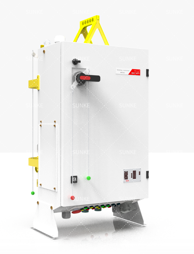
This framework defines structured practices to prevent sudden failures and to sustain repeatable weld quality on resistance welding lines. It is written with formal clarity and practical emphasis, so the maintenance team will know where to act first. Early reference to the control element is necessary: verify the resistance welding controller configuration and its environmental mounting as part of the very first assessment.
Scope and Rationale
Scope: power modules, secondary circuit, electrode system, cooling and signal interfaces for medium- and high-current resistance welders. Rationale: well-structured preventive maintenance reduces drift, limits thermal damage, and preserves electrode life. This framework is suitable for single-station machines and multi-gun production lines used in heavy manufacturing.
Framework Overview — Four Pillars
The logic follows four pillars that must be integrated: inspection, electrical health, mechanical integrity, and process verification. Treat these pillars as interdependent: neglect in one will create faults in others.
Inspection Pillar — Routine Observations
– Visual checks of insulation, connectors, and busbars for discoloration or deformation. – Confirm contact surfaces are free of scale and consistent wear patterns. – Check ventilation and filter condition; blocked airflow accelerates component stress. – Monitor indicator LEDs, alarm logs, and thermal signatures during idle and production cycles.
Electrical Health Pillar — Measurements and Tests
Precise electrical checks prevent hidden deterioration. Measure and record: secondary circuit resistance, contact resistance at electrode holders, and continuity of current return paths. Use calibrated meters and log baselines to detect gradual changes. Where modulation controllers are present, verify waveform shape and timing; variability here affects energy deposition.
Diagnostics and the Power Module
Assess the actual welding power supply module under load and at idle. Capture simple but telling diagnostics: voltage drop across contacts during a test weld, ripple on DC link, and surge absorber activity. If ripple or abnormal transients appear, isolate the power module and test capacitors and switching elements with manufacturer-approved procedures. Record all measurements for trend analysis.
Mechanical Integrity Pillar — Alignment and Force
Electrode alignment and force application are mechanical determinants of weld quality. Check arm parallelism, actuator travel limits, and force transducer calibration. Replace worn pivots and bearings before they permit misalignment. Use simple gauges to verify repeatable squeeze and hold times under typical production load.
Process Verification Pillar — Calibration and Control
Calibrate process parameters against a known good part: collapse, nugget size, and peel test results. Confirm controller recipes map exactly to the machine hardware and are protected against unintended edits. Keep one validated recipe per part and log deviations immediately.
Weekly, Monthly, Annual Task Matrix
– Weekly: visual inspection of cables, electrode faces, filters; quick test weld and log results. – Monthly: measure contact and secondary resistances; verify cooling flow and fluid condition. – Quarterly: verify waveform fidelity, check capacitor ESR trend, update control software if patch verified. – Annual: full teardown inspection of power module, replacement of worn busbar joints, calibration of force and timing instruments.
Common Pitfalls and How to Avoid Them
– Relying on indicator lights alone: use measurements rather than lamps. – Delayed electrode replacement: replace by wear pattern, not by schedule only. – Poor grounding practice: ensure ground returns are as robust as supply conductors. – Ignoring thermal history: track temperature excursions and correlate with electrical drift.
Tools, Records, and Personnel Practices
– Necessary tools: precision milliohm meter, thermal camera, oscilloscope for waveform capture, calibrated force gauge. – Records: maintain time-series logs for resistance, ripple, and calibration dates. – Personnel: assign clear responsibilities; a single point of accountability shortens diagnostic time.
Implementation Checklist (Compact)
– Baseline measurements recorded for power module and secondary circuit. – Weekly visual and ventilation checks scheduled and logged. – Calibrated instruments available and certified. – One validated process recipe per product line locked in controller. – Training session completed for operators on identifying early electrode failure.
Closing Synthesis
Follow this framework with discipline: inspect visually, measure electrically, maintain mechanically, and verify the process. This disciplined approach reduces unplanned downtime and stabilizes production quality, consistent with field experience observed in automotive plants in Detroit. When maintenance teams adopt these habits and document trends, the result aligns with supplier guidance and practical performance often seen with Sunke.