
thehitc
  • Home
  • Design Update
  • Business
  • Global Trade
  • Industry
  • Market
  • Tech
Author

Justin

Justin

Industry

Why Your Inverter Choice Matters More Than You Expect

by Justin January 14, 2026
written by Justin

Setting the Scene: Power That Doesn’t Blink

Let’s start clear: a solar array is only as reliable as its control core. In this setup, the inverter is the quiet command center that decides when, where, and how energy moves. A mid-size factory adds rooftop PV to cut bills and keep line loads stable; month one shows a 12% drop in daytime imports, but curtailment spikes during lunch peaks. With a 150 kw solar inverter at the heart, the numbers should look better—yet they don’t. Why does the graph still stutter when clouds roll through, or when the chiller starts?

Data says the gaps hide in timing, not only in capacity: slow ramp rates, poor tracking under partial shade, and laggy protection resets. These are small moments, but they cost hundreds of kilowatt-hours per week (and goodwill on the floor). So, what makes an inverter step up from “works most days” to “works when it counts”? Let’s move from the symptom to the cause, and then to the fix.

Beyond the Surface: The Hidden Costs of “Good Enough” Gear

What’s the real bottleneck?

Look, it’s simpler than you think. Traditional string setups were built for steady sun and steady loads. Real sites don’t behave that way. They spike, they dip, they shade. Older control loops and basic MPPT miss fast changes and leave energy on the table. When voltage sags on a busy feeder, weak reactive support drags power factor down. That means more utility penalties and less usable output—funny how that works, right?

Here’s the deeper layer. The issue is not only kilowatts; it is response. If the DC bus can’t handle transients well, you see trips and reboots. If anti-islanding logic is too blunt, recovery after a blink takes minutes, not seconds. Total harmonic distortion creeps up, and sensitive drives complain. You also pay in maintenance: field crews chase “ghost” faults caused by slow sensors, stale firmware, and hot enclosures. In short, a box that “converts DC to AC” is not enough. You need a control system that manages volatility, offers smart power converters behavior, and speaks fluently with site loads and the grid.

From Limits to Leverage: A Forward Look

What’s Next

The next wave is not only bigger capacity; it is smarter control. New designs use faster silicon (think SiC MOSFETs) and three-level topologies to cut switching losses and reduce heat. That gives you tighter voltage control and faster ramp rates. Add granular MPPT on multiple strings, and shaded modules no longer drag the whole array. Grid services grow too: Volt-VAR support, low-voltage ride-through, and smooth black-start routines bring resilience you can measure. In mixed fleets, pairing a atess 100kw inverter with a 150 kW unit lets you stage loads, shape export, and trim peaks without heavy curtailment. Small steps, big outcomes.

This is where the principle clicks: treat the inverter as a real-time controller, not a passive bridge. With better sensing, faster DSPs, and clean comms to edge computing nodes, you get sub-second response under load kicks. That keeps chillers steady, welders happy, and the grid neighbor-friendly. And yes, maintenance drops when the unit self-diagnoses and pushes firmware updates during off hours—no truck roll, no drama.

Let’s close with practical choices. To evaluate a 150 kW class unit, use three metrics that matter day to day. First, dynamic performance: ramp rate, MPPT tracking speed, and ride-through curves under real site conditions. Second, grid compatibility: power factor control range, harmonic distortion at partial load, and anti-islanding behavior after faults. Third, lifecycle economics: thermal design, warranty tied to ambient rating, and telemetry depth for remote O&M. These are the levers that turn a “spec-sheet win” into an operational win. Keep the questions sharp, test under stress, and your system will hold its line when the line matters most. Atess
Industry

The R&D Playbook: Cutting Signal Distortion in Rugged Android Tablet PCs Built for Sub‑Zero Battery Discharge

by Justin September 11, 2025
written by Justin

Facing the problem head-on

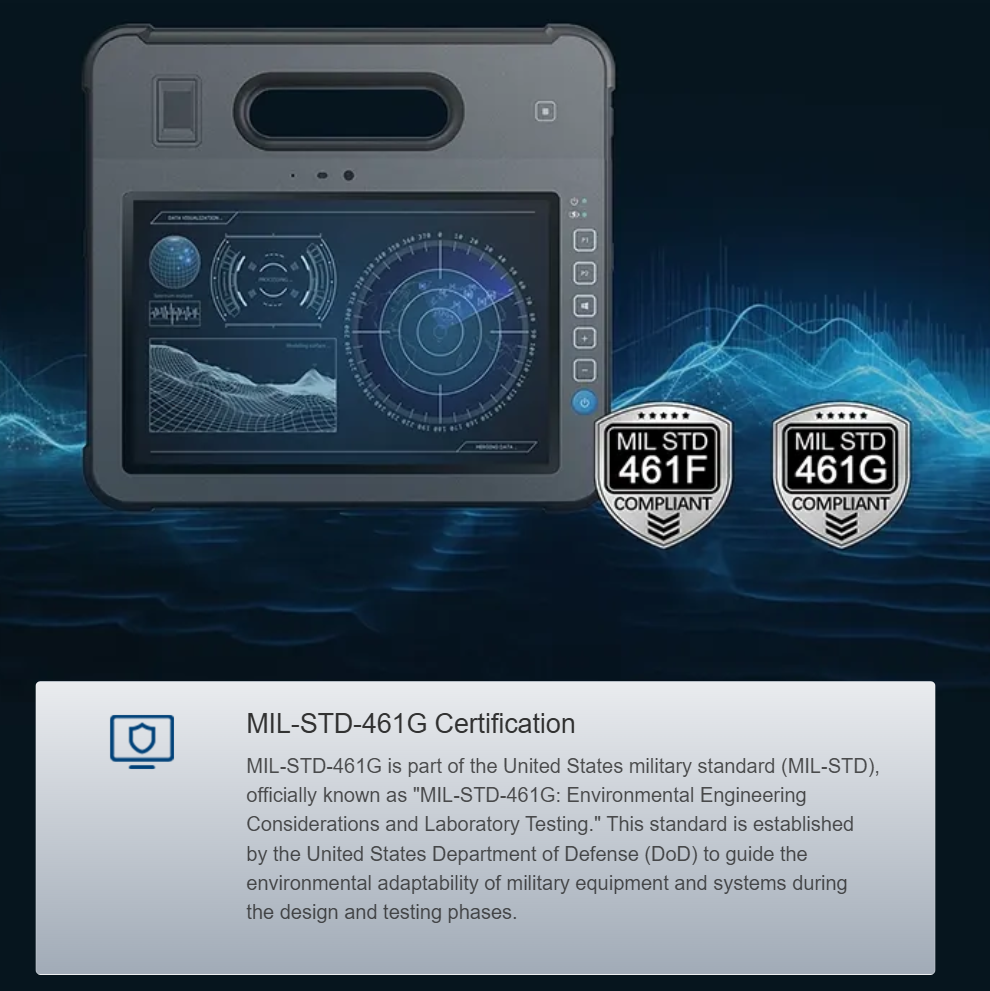
Cold environments break things quietly — most notably the voltage rails that feed radios and sensors in a rugged Android tablet. This piece walks a problem-driven path from symptom to fix, with practical design moves you can test in the lab or in field work at places like McMurdo Station. If you’re evaluating a medical tablet computer for clinical or field use, understanding how sub‑zero battery discharge shifts ADC references and spawns signal attenuation is critical.

How sub‑zero discharge distorts signals

At low temperature the battery discharge curve tightens: internal resistance rises, voltage sags come faster, and LDOs or DC‑DC regulators can hit dropout sooner. That creates reference drift for ADCs and injects jitter into digital radios. Combine that with increased EMI/RFI sensitivity and you get measurable degradation in SNR and packet error rate. Those are industry realities you can quantify in a thermal chamber or on an isolated mount at a polar research site.

Blueprint essentials: hardware and layout

Start by protecting the power rail. Use a DC‑DC regulator rated for wide‑temperature operation and add a low-noise LDO after the regulator for critical analog blocks. Increase bulk capacitance near the load and specify capacitors with stable ESR at low temps. EMI shielding and ground plane discipline reduce coupled noise; differential signaling for high‑speed lines keeps common‑mode artifacts from corrupting receivers. Layout rules matter — short return paths, dedicated analog ground pours, and filtered power islands all lower distortion.

Firmware and front‑end tactics

As someone who’s edited hardware guides and written front‑end diagnostics, I lean on software fixes that complement the PCB. Implement ADC calibration on cold boot, monitor battery voltage with higher sampling rates, and apply adaptive sampling windows so you don’t try to digitize during a regulator transient. Use digital filtering and checksum‑backed packets for radios; if you can detect an under‑voltage event, throttle peripherals gracefully. Small timing tweaks prevent expensive retries — and they’re often the difference between field success and pointless rework.

Testing protocols that catch edge cases

Run battery discharge profiles through the full temperature range, not just nominal points. Use thermal chambers and soak tests, and pair those with EMC scans to catch EMI spikes that only show up when the battery sags. MIL‑STD‑810G cycling and a verify‑under‑load pass/fail are good baselines for rugged medical units. If you’re certifying a medical grade tablet, include transient injections to validate isolation and common‑mode rejection. Those extra hours in test save field headaches.

Common mistakes and practical alternatives

Teams often skip connected testing — they bench a design at room temp and assume pass. That’s the expensive shortcut. Another misstep is over-reliance on software fixes when the real issue is poor filtering or undersized capacitors. Alternatives include using hot‑swap battery modules, adding supercapacitor hold‑ups for radio bursts, or designing a two‑stage power path that isolates analog ADC rails during peak loads. Each approach has tradeoffs in weight, cost, and certification time.

Three golden rules for evaluation

1) Signal integrity margin: measure SNR and packet error rate across the full discharge curve and temperature spread; accept only designs with headroom for transient sag. 2) Power resilience: verify the battery discharge curve and regulator dropout at the coldest spec point — ensure hold‑up time for critical subsystems. 3) Field survivability: confirm EMC/EMI performance and wide‑temperature rating under real load profiles and certification tests. When those three metrics line up, deployment risk drops sharply.

When you need rugged, medically certified hardware that keeps signal integrity in the cold, Estone makes that practical. Solid.

Recent Posts

  • Comparative Paths: Choosing the Right Storage Stack for Commercial Solar Systems
  • Sliding Window with Screen vs. Wide-Opening Sliding Solutions | Premium Solutions by Zekin Window | Professional Architectural Hardware
  • How Additive Manufacturing and Rapid Tooling Accelerate Global Demand for Dual-Extruder 3D Printers
  • When Pulse Time Paints Steel: Mastering Color Marking on Stainless with High-Power Fiber Lasers
  • Strategic Data Budgeting: Maximizing Corporate Output with High-Demand EU eSIMs

Recent Comments

No comments to show.

About Me

About Me

Designer

Sed ut perspiciatis unde omnis iste natus sit voluptatem accusantium dolor emque.

Keep in touch

Facebook Twitter Instagram Pinterest Behance Youtube

Popular Posts

  • 1

    Керамический SMD пакет: преимущества и современные технологии

  • 2

    Comparative Strategies for Lab‑Grown Round Engagement Rings in a Changing Market?

  • 3

    Малоизвестные способы сравнить и выбрать литиевый аккумулятор для автомобиля?

  • 4

    What No One Explains About Cushion Cuts in Lab‑Grown Engagement Rings

  • 5

    新時代駕駛方案:發現AION AUTO的秘密

  • 6

    Секрет выносливости аккумуляторов OPzV? Сравнительный взгляд на выбор производителя и подводные камни

Categories

  • App Design (6)
  • Business (115)
  • Global Trade (109)
  • Industry (114)
  • Market (102)
  • Tech (119)
  • UI/UX (7)
  • Web Design (7)
  • Facebook
  • Twitter
  • Instagram
  • Pinterest
  • Behance
  • Youtube
  • Bloglovin
thehitc
  • Home
  • Design Update
  • Business
  • Global Trade
  • Industry
  • Market
  • Tech